


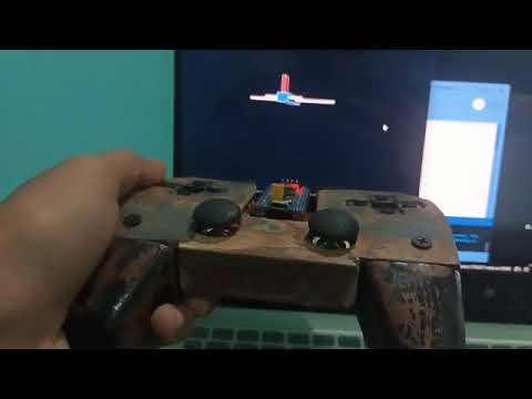
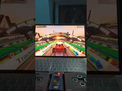
A handmade USB HID gamepad and reusable test pad built from scratch using STM32F103C8T6 "Blue Pill", PS2 joystick modules, MPU6050 gyro/accel, and 12 tactile buttons. Tested and working in real games.
I needed a reusable gamepad and test pad for my STM32 projects — something I can use for flight sims, FPS games, and future experiments without rewiring buttons, joysticks, and pots on a breadboard every time. It started as a hobby project and turned into a fully functional controller that I use daily.
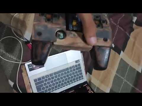
It looks rough — but not from heavy use. The finish is rough because this was built with whatever was available: leftover scrap wood from furniture (that would have gone into a bonfire), leftover paint from the workshop, and large furniture tools instead of precision crafting tools. No 3D printer, no professional woodworking tools, no fresh wood. Everything was improvised with what was at hand.
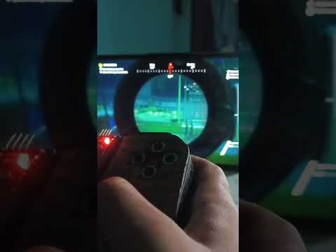
The electronics and firmware are the real focus here. The cosmetic finish is secondary — that's what v2 is for. Tested in:
- Sniper Ghost Warrior 3 (FPS)
- War Thunder (flight sim)
- FlightGear (flight sim)
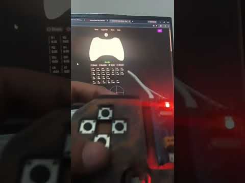
- gamepad-tester.com (browser HID test)
- vJoy (virtual joystick driver)
| Component | Qty | Description |
|---|---|---|
| STM32F103C8T6 "Blue Pill" | 1 | Main MCU, 72MHz, 64KB Flash, 20KB RAM |
| PS2 Joystick Module (KY-023) | 2 | Cheap/basic analog dual-axis potentiometers (thumbsticks) |
| 10kΩ Trim Potentiometer | 2 | Mini pots used as analog shoulder triggers |
| Tactile Push Buttons (6mm) | 12 | Momentary switches for digital inputs |
| USB Connector | 1 | Micro-USB or USB-C (board dependent) |
| ST-Link V2 | 1 | For flashing firmware |
| Hookup Wire | - | For connections |
Note: Buttons use the STM32's internal pull-ups (no external resistors needed). Cheap PS2 joystick modules and trim pots tend to drift — per-axis calibration in firmware fixes this.
| Axis | Pin | Source | Calibration |
|---|---|---|---|
| X (Left Stick X) | PA0 | PS2 Joystick | min=0, max=3095, reversed |
| Y (Left Stick Y) | PA1 | PS2 Joystick | min=0, max=2595, reversed |
| Z (Right Stick X) | PA2 | PS2 Joystick | min=0, max=4095, reversed |
| Rx (Right Stick Y) | PA3 | PS2 Joystick | min=0, max=4095, reversed |
| Ry (Left Trigger) | PA4 | 10k Trim Pot | min=0, max=4095, reversed |
| Rz (Right Trigger) | PA5 | 10k Trim Pot | min=0, max=4095, normal |
| Button | Pin | Bit |
|---|---|---|
| BTN1 | PB0 | 0 |
| BTN2 | PB1 | 1 |
| BTN3 | PB3 | 2 |
| BTN4 | PB4 | 3 |
| BTN5 | PB5 | 4 |
| BTN6 | PB8 | 5 |
| BTN7 | PB9 | 6 |
| BTN8 | PB10 | 7 |
| BTN9 | PB11 | 8 |
| BTN10 | PB12 | 9 |
| BTN11 | PB13 | 10 |
| BTN12 | PB14 | 11 |
This was built with zero budget using whatever was available in the workshop:
| Material | Source |
|---|---|
| Body | Scrap wood from furniture (leftover pieces that would've gone into a bonfire) |
| Paint | Leftover paint from the workshop — not bought for this project |
| Tools | Large furniture tools — no precision crafting tools, no Dremel, no 3D printer |
| Screws | Whatever was lying around |
| Wire | Standard hookup wire |
No fresh wood was purchased. No professional tools were used. No 3D printer. The enclosure was carved and assembled by hand using basic workshop tools. The finish is rough because of the tools and materials available, not because of neglect or heavy use. This is a v1 functional prototype — the focus was on getting the electronics and firmware right. v2 will have a proper enclosure.
The gamepad uses a custom USB HID descriptor (14-byte report):
Report Layout (14 bytes):
[0-1]   Axis X   (16-bit, 0-4095)
[2-3]   Axis Y   (16-bit, 0-4095)
[4-5]   Axis Z   (16-bit, 0-4095)
[6-7]   Axis Rx  (16-bit, 0-4095)
[8-9]   Axis Ry  (16-bit, 0-4095)
[10-11] Axis Rz  (16-bit, 0-4095)
[12]    Buttons low byte  (bits 0-7)
[13]    Buttons high byte (bits 8-11) + 4-bit padding
No external libraries needed — raw USB HID class, compatible with Windows/Linux without drivers.
The original firmware built with PlatformIO using bare-metal STM32 HAL. Pure analog gamepad — 6 ADC axes + 12 buttons. MPU6050 I2C was attempted but failed due to STM32F103 hardware I2C bugs.
# Clone the repo
git clone https://github.com/forgeVII-org/DIY-Rough-Gamepad.git
cd DIY-Rough-Gamepad/firmware

# Build
pio run

# Flash via ST-Link
pio run -t upload- PlatformIO CLI or VS Code + PlatformIO Extension
- ST-Link V2 programmer connected to the Blue Pill
The Arduino approach uses Roger Clark's Arduino_STM32 core with USBComposite library, which solves the MPU6050 I2C issue that plagued the HAL version. The Arduino Wire library handles I2C differently and works around the F103's hardware I2C bugs.
Install these in Arduino IDE:
- Arduino_STM32 core — Roger Clark's repo or via Board Manager
- USBComposite_for_STM32 library — Arpruss repo (also bundled with Arduino_STM32)
| Variant | Folder | Focus | MPU | Analog Axes | Triggers | Yaw Reset |
|---|---|---|---|---|---|---|
| Original | arduino/original/ |
Full gamepad — buttons, pots, MPU all on breadboard | X/Y/Z (yaw, pitch, roll) | 6 (all PA0-PA5) | Combined (single axis) | Yes (PB12+PB13+PB14) |
| v2 | arduino/v2/ |
Gyro/tilt-based games — yaw control priority | X/Y/Z (yaw, pitch, roll) | 3 (no right stick X) | Separate | Yes (PB12+PB13+PB14) |
| v3 | arduino/v3/ |
Simple pot/button games + tilt support | Roll + Pitch only | 6 (all PA0-PA5) | Separate | No |
| Axis | Original | v2 | v3 |
|---|---|---|---|
| X | MPU Yaw | MPU Yaw | Left Stick X |
| Y | MPU Pitch | MPU Pitch | Left Stick Y |
| Z | MPU Roll | MPU Roll | Right Stick X |
| Rx | Left Stick X | Left Stick X | Right Stick Y |
| Ry | Left Stick Y | Left Stick Y | Left Trigger |
| Rz | Right Stick X | Right Stick Y | Right Trigger |
| Slider | Combined Trigger | Right Stick Y | MPU Roll |
| Slider | Right Stick Y | Separate Trigger | MPU Pitch |
- Open the
.inofile in Arduino IDE - Select board: Generic STM32F1 Series → BluePill F103C8
- Upload via USB DFU or ST-Link
# Or via STM32CubeProgrammer CLI
# Arduino IDE handles compilation and uploadarduino/
├── original/
│ └── original.ino # Full gamepad — MPU + 6 analog + combined trigger
├── v2/
│ └── v2.ino # Gyro-focused — MPU + 3 analog + separate triggers
└── v3/
└── v3.ino # Pots + buttons + roll/pitch on sliders


Axes can be calibrated in 3 ways:
Each axis has hardcoded min/max values in the firmware. Edit these directly in the .ino file to match your physical pot's range:
// In the analog read section, adjust the >> shift or add min/max mapping
// For example, if your pot reads 100-3800 instead of 0-4095:
// val = map(val, 100, 3800, 0, 255); // or 0-1023 for 10-bitUse vJoy to calibrate axes in software:
- Install vJoy and vJoy Conf
- Create a virtual device matching your axis/button count
- Map your physical gamepad to vJoy using vJoyMapper or Universal Joystick Remapper
- Calibrate each axis through vJoy's wizard
Use apps like xoutput.exe to map and calibrate:
- Open xoutput.exe
- Select your gamepad device
- Calibrate each axis — set deadzone, range, and direction
- Save profile — maps to an Xbox 360 controller that most games recognize
Tip: For quick testing, use gamepad-tester.com in a browser — it shows all axes in real-time without installing anything.
MPU axes drift over time (no magnetometer to correct yaw). Use the reset combo to recenter all MPU axes to 0:
Press PB12 + PB13 + PB14 simultaneously (3 buttons together) → yaw, roll, and pitch reset to center.
This works in original and v2 variants only. v3 does not have yaw.
- ADC Reads — 6 analog channels from PS2 joystick potentiometers read via12-bit ADC, calibrated per-axis for each physical pot's range
- Button Matrix — 12 tactile buttons using STM32's internal pull-ups, active-low, no external resistors needed
- USB HID — Raw USB HID gamepad class, 14-byte report sent every 10ms, appears as standard joystick on Windows/Linux
- No Drivers — Uses USB HID class natively — works out of the box with vJoy, Windows Game Controllers, gamepad-tester.com, and games
The PlatformIO/HAL firmware could not communicate with the MPU6050 over I2C (known STM32F103 hardware bug). The Arduino approach using Wire library + Arduino_STM32 core works around this — MPU6050 is now fully functional with roll, pitch, and yaw via adaptive complementary filter.
Three Arduino variants are available in arduino/ — see Arduino (MPU6050 Working) section above.
Some axes reach max value before the joystick reaches its physical stop. This is due to cheap PS2 potentiometer's rotation range not matching the joystick's mechanical travel. Per-axis calibration (min/max + optional reverse) fixes both the range mismatch and center drift common in budget joystick modules.
Version 2 will be a complete redesign using ESP32-S3 with:
| Feature | Status |
|---|---|
| ESP32-S3 with native USB HID | Planned |
| MPU6050 gyro/accel working | Done (via Arduino approach on Blue Pill) |
| Bluetooth gamepad mode | Planned |
| Wireless 2.4GHz mode | Planned |
| LiPo battery with charging | Planned |
| Better enclosure design | Planned |
| OLED status display | Planned |
| RGB LED indicators | Planned |
| Multi-mode (gamepad / flight / custom) | Planned |
| IR remote control (TV/STB) | Planned |
- Re-flash firmware
- Check USB D-/D+ wiring
- Try different USB port
- Check PA0-PA5 wiring to joystick modules
- Verify 3.3V power to joystick VCC
- STM32 internal pull-ups are enabled in firmware — no external resistors needed
- Verify buttons are wired active-low (pin to GND through button)
- Re-flash firmware
- Uninstall device in Device Manager and replug
- Check USB descriptor matches (14-byte report)
This project is licensed under the MIT License — see LICENSE for details.
- STMicroelectronics for the STM32 HAL and USB device library
- PlatformIO for the build system
- The STM32 community for USB HID implementation guides
- My AI assistant for debugging and code generation
Built as a hobby project. It's rough, it's used, and I'm proud of it.